Parametric Modelling In Maya?

Hi there

I was just wondering if there is anybody that knows where I can find some information about building parametric modelling in Maya. I need it for an architectural structure so I can test things like light and wind! But I can't seem to find anything online !

Thanks

All things that describe on how to animate stuff in Maya talk about how to do parametric modeling*. But let us eb e abit simpler: What exactly do you want to happen?

QUOTE
and wind

That might be hard mayas not fem application.

*maya users just don't usually call it parametric, we are not using engineering terminology

Hi Joojaa

First of all thank you for your quick reply I really appreciate it! You see the problem is that I dont know enough about what I am doing. I am trying to build a structure/building where I would like to test how it reacts to wind and maybe light as well. I have heard people talking about that I should use parametric modelling in Maya to do that, but I dont know how? Is there any difference between normal modelling and parametric modelling?

Thanks

QUOTE
Is there any difference between normal modelling and parametric modelling?

Yes, parametric modeling is used in architecture for "non standard forms" in architecture that means crudely that the building components are not all the same, moreso they are all different and use CNC techniques to be built instead of the "standard" uniformed components. this is however difficult to model and involves either heavy use of scripting or modeles in which every element is hierarchically connected (loft two curves and change one then the entire loft changes... but then on a building scale) there are some software packages made specifically for parametric modeling of buildings: generative somponents, catia (or "Digital Project" by gehry technologies) these have built in elements to also prepare your model for CNC. you can use MAYA, i do ( i teach at the TU Delft, faculty of architecture, department Hyperbody, for Kas Oosterhuis) but usually only for sketching and defining and exploring initial shapes, keeping track of the component connections is really tough in MAYA. however scripting (im using python) does work really nice for parametric designs. Though most of our students prefer rhino.
I just posted an animation of my workshop (in the newbie gallery) which ill give, from mon the 23rd of feb til wed. the 25th, in which i will teach the students how to make a parametric model of a facade in which each facade element willl interact with environmental conditions( wind rain air pressure sun whatever) using Virtools and MAYA , you are free to join if you want...its in Delft NL at 10:00....dont be late!

QUOTE
I would like to test how it reacts to wind and maybe light as well.

there is a sun simulator to test the light performance of your building here:

http://toi.bk.tudelft.nl/index.php?module=...ails&sID=40

for wind you can use one of the premade particle systems found somewhere in the visor its called "windtunnel 3D" a bitch to render though i recomend the software renders for the particles. getting it right in mental ray is really a waste of time and the trick of scientific representation is NOT to tell that you did it in MAYA and NOT to make it look to good... just make software renders and pretend you used real CFD software.

Hi there

Sorry for the late reply!

Thank you for your description of the parametric modeling! So there is a different between parametric and normal modeling! Do you use different tools to model it with or is it the same tools? As you can see, I am still a bit confused on how I would model something in parametric! Do you know if there is any online tutorial that includes parametric modeling? Sorry for asking these questions, but as you probably know, I am a newbie!

Thank you for the mel script! I will definitely try it out once I figure out how to use it

Also, thank you very much for the invitation to your tutorial. I would love to join, but unfortunately I dont live in The Netherlands ;(

Btw. I couldnt find your animation in the newbie gallery!

QUOTE(kmkr03 @ 02/17/09, 10:41 PM) [snapback]301091[/snapback]
So there is a different between parametric and normal modeling!

Well in maya there isn't. And neither is there any difference in some for the cae apps like catia, pro|e, solidworks etc.

The difference is in how you think your modeling up, even if you do not intend to make parametric modeling maya would make up parameters for the model. Its just that the parameters don't reflect to what you would like to use as values for. So its a more of a design issue than a modeling one.

Do this

  • make sure your history is on!
  • create polygon cube
  • Select top face
  • extrude
  • extrude again
  • select cube
  • Now in the channelbox observe and expand input for extrudeFace1
  • Note how you can ajust the values on after the fact
  • Theese are parameters of the object, maya users calle them channels, they relate to nodes and the nodes make up changes in mayas hitory and geometry. Now by hooking up things intteligently you can end up with parameters that describe something. So you maya test differebt kinds of mathematical functionality on a model without doing a lot of rework to fix small changes in the design process.

    Now this si how you animate in maya. And EVERYTHING in maya works like this so ergo you can do all things parametrically. Just maya users don't call these parameters. It is customary to call this sort of thing procedural modeling in the cg industry, because we didn't call things parameters like manufacturing industry did. The two terms mean the same thing.

    Ok now for a more practical example:

  • make a nurbs cube.
  • apply a bend on it
  • animate the bend
  • aniamte cube to move along some axes during the timeline.
  • make a animated snapshot
  • change the anim curves for the channels see how the shape varies.
  • This enables you to do complex shapes out of simple manufacurable parts. And explore the ideas quickly.

    QUOTE
    keeping track of the component connections is really tough in MAYA.

    Thats just because you know catia much better than maya. For me its not much harder to keep track of connections in maya than it is in any of the cae applications. its just the the description language is a buit different.

    Maya does show all the logical connections in the hypergraph. So i can track them there.

    Anyway i do agree mayas not really the tool for this as you relly need to use nurbs en masse and the cae applications are MUCH better at this, especially when its time to get your model built. Tough certain things are very trivial to do in maya that are near impossible to do in most of the CAE apps.

    Ive helped to use maya to average the incoming energy levels on courtyard throughout the day as evenly as possible, by hooking a feedback loop of a vertex color render to parameters to new renders and then iterate 1000 times, it gets very interresting results

    Hi Joojaa

    Sorry for the late reply! Been really busy lately, so havent really had time to anything!

    Anyway, thank you for your explanation! I think I finally understand it now So parametric modelling is actually adjusting only the parameters of an object to affect its shape, right?

    Once again thank you! Now I will try the two examples you mentioned

    QUOTE(kmkr03 @ 02/24/09, 11:42 PM) [snapback]301633[/snapback]
    So parametric modelling is actually adjusting only the parameters of an object to affect its shape, right?

    Yes, but more accurately modelling in way so you get the parameters you need for the thing you want to adjust. It doenst make much sense to have random parametes now does it.

    Ok, I am playing around with lofting at the moment and that works very well with editing the lines afterwards and the lofting follows! My question is

    post got cut of try to avoid using weird characters.

    Dammit, why does my post always get cut! It is really annoying!

    Anyway, what I was trying to say was that I have been playing around with lofting the last couple of days and find it really nice! One thing I would like to know is how to move your lines (the ones used for the lofting) and the lofting itself together! When I try to move them, they do not follow each other! So when I move them, the shape gets distorted!

    QUOTE(kmkr03 @ 03/05/09, 11:11 PM) [snapback]302379[/snapback]
    Dammit, why does my post always get cut! It is really annoying!

    It will if you copypaste stuff form anything even remotely typesetting.

    QUOTE
    One thing I would like to know is how to move your lines (the ones used for the lofting) and the lofting itself together!

    You dont you move just the lines The loft will move with them! Well technically you COULD move the loft oppsoite way but makes no sense. BUt yes you can put them in same hierarchy anyway, just make sure the lofts atrasform does not inherit trasforms (its a option)

    Why is keeping 2 things that are allready together, imprative to be kept even more together on higher levels

    Damn I feel stupid now! Thanks for teaching me only to move the lines and not the whole thing!

    While I am at it, I have some more questions! But first I would just like to say THANK YOU! I really appreciate that you take you time to answer my newbie questions! I must admit I feel bad about asking all these questions all the time, but I am just happy that there are someone like you that a so kind to help

    1. How do I project a pattern onto a curved surface? Lets say I have a diamond shaped pattern that I have made in illustrator and imported into Maya. I now have the outlines of the pattern, and that pattern I would like to put onto a curved surface. How would I do that?

    2. Another thing that I can not seem to figure out, is how to extrude a lofted surface. I know in 3d max you have a thing called shell modifier, that quite easily can do thin, but I do not know how to do it in Maya?

    Ohhh, I forgot to mention that the curved surface is NURBS! It is really a lot more difficult to texture NURBS than polygon, or am I wrong. Cant seem to find any good tutorial on how to texture a curved surface in NURBS anywhere!

    QUOTE(kmkr03 @ 03/07/09, 11:25 PM) [snapback]302533[/snapback]
    It is really a lot more difficult to texture NURBS than polygon, or am I wrong.

    Well i find texturing nurbs in general as easy as polygons if not slightly easier since i can skip one step wich sint related to texturing just modeling.

    But yes ibve never understood this comment. Its as if somebodys missing a piece of the puzzle in their head.

    QUOTE
    1. How do I project a pattern onto a curved surface?

    In hyopergraph drop a project node into your shader.

    QUOTE
    2. Another thing that I can not seem to figure out, is how to extrude a lofted surface.

    Well use polygons (you can simplyvconvert nurbs to poly) if you want to do something like shell even max works on polygons.

    But yes you can take a surface offset and loft the edges of your surfaces. (i had a script to do this somewhere.)

    Hi JooJaa

    Once again, thank you for your kind reply! I really do appreciate it!

    I have now tried to look into the hypergraph, but I still cant seem to get it to work they way I want it to.

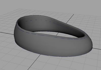
    Lets say I have a structure like the image below and would like to apply a pattern like the second image. It has to tile/repeat is self and follow the shape without being distorted.

    One way is of cause to do it with just a texture file, but I would be amazing if I could do something like this.

    This is done in Rhino and it somehow projects the texture to the surface.

    flow-along-surface

    Anyway, if I just apply a texture file, I still have trouble getting it to fit and follow the shape (different heights of the structure) without getting distorted!

    This is not a projection!

    QUOTE(kmkr03 @ 03/11/09, 02:41 AM) [snapback]302764[/snapback]
    Anyway, if I just apply a texture file, I still have trouble getting it to fit and follow the shape (different heights of the structure) without getting distorted!

    Disortion is caused by the parametric length of the uv of the map. So if youmake a section that is 1 long and 12 wide then your 1 long 1 wide oject will stretch it to fit that exact surface irrespectively of the roigfinal aspect. Now if you have a uneven distribution of parameters (curves) then you will get a uneven distribution of the default parameter space.

    Also the rhino version works very easily since the surface is streched more or less to fit the size of the texture and has e very even parameter space. But your surface has a uneven parametrisation. and thus the uve map will be uneven. If you made the exact same surfecae as in rihno youd have no problems. Its actually made for a even parameter space. You cant jsut have more points at certain locations and less in others it streches the parameters.

    TRy enabling under the shape object atribute editor tab, the fix texture wrap option. It will try to reparametrize the curve more evenly. NOTE: It will only work in render not viewport. (and wont work in mr unless you have relatively new maya) AMMENDUM: It will work in viewport if you put high quality texturing on

    You could rebuild the parameter length tough but thats a bit tricky, and youd need to know a lot more than you do to do that.

    Hi there, sorry for the late reply! Thank you for clearing that out for me I have now had some time to try out different solutions for the texture mapping, and found that the cylindrical uv mapping worked best. Still not correct, but it will be ok for now!

    Once again, thank you so much for taking time to help me out!